2021-12-10

To increase the production efficiency, many manufacturers are searching for a system to measure over 4,000 individually machined components a day. It could be better if the system could be integrated into an automatic production line to measure shaft-shaped, largely axially symmetrical workpieces. To accomplish this, we evaluated various methods and inspection systems for the process, including the following:
Manual Go/No Go Gages, which were deemed too inflexible for varying part types and diameters\height.
Manual Snap Gages and Dial Indicators; while very economical, they proved very slow and dependent upon operator performance.
CMM systems were found to be too expensive and slow to meet the production requirements. Audit inspection proved very reliable, but the requirement was for 100% inspection, which is not realistic with a CMM system.
The key component missing from the above methods was the ability to provide 100% inspection at high throughput, which is not sustainable for many measuring systems. The solution was found in Image measuring system, which offers speed, accuracy and flexibility.
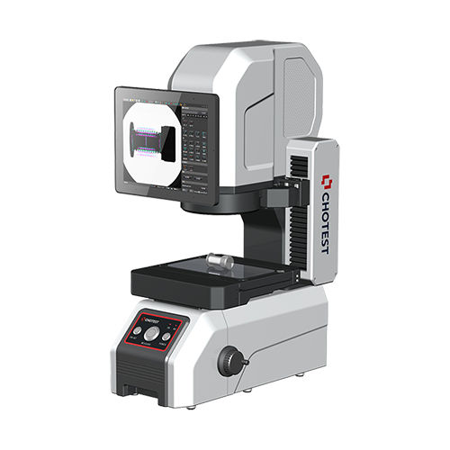
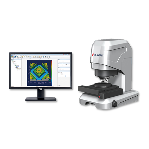
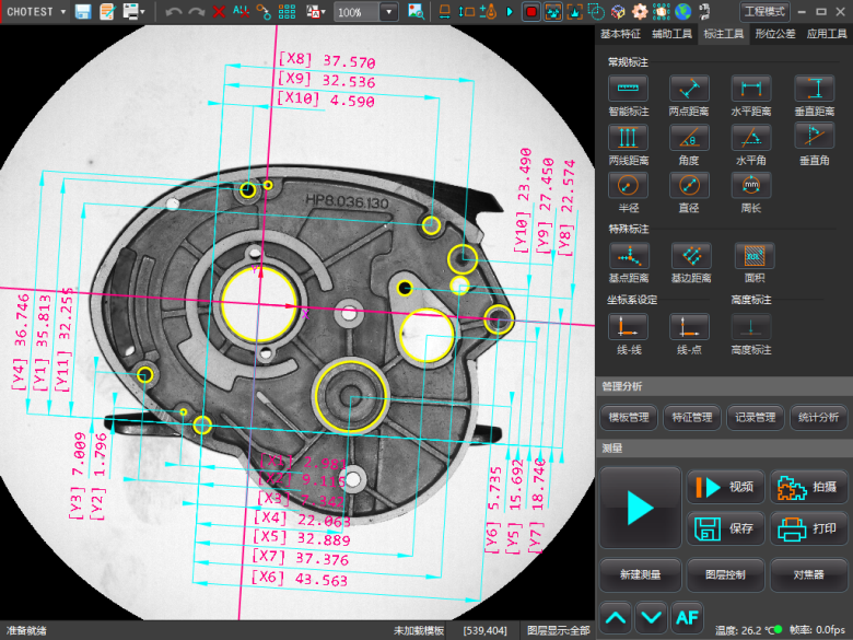
Optical 2D/2.5D systems are based upon state-of-the-art area image sensors and can perform many micrometric-precision checks on parts with an unprecedented speed. These systems use multiple image sensors integrated in fixed positions across the product structure to cover the entire measurement range so that neither the image sensors nor the part being measured must travel along the Z-axis. This means that images acquired by different sensors are perfectly combined together, resulting in one single image of the part with zero discontinuities or gaps at the stitching edges. The measurements are defined, configured and displayed on the graphic user interface shown on the touchscreen monitor built into the optical system.

The 2D/2.5D Optical Operating Principle
The basis of this optical technology is projecting the shadow of the edges of the part to be measured over a linear array of photodiodes (CCD) by means of a collimated beam of light. The dark-light and light-dark transitions are localized on the CCD sensor having subpixel resolution and correlate to the dimensional value of the shadowed area.
The transmitter produces visible blue light (light (λ=460nm), which is generated by an LED. This gives the emitter strength, reduced dimensions, long life (20,000 hours), absence of thermal drift and regulated power emission through feedback from the power supply. The light rays are expanded—then collimated—by a stationary lens and sent to the part to be measured. The transmitted light is gathered by the receiver, spatially filtered and projected onto the CCD sensor. A one-dimensional image on the CCD sensor is the reverse and, therefore, a negative of the scene viewed by the emitter.
The CCD is electronically read and the signal processed using special algorithms, allowing localization of the dark-light transitions on the CCD to be determined and correlated with the dimensional value of the shaded areas corresponding to the profile of the part being measured. To maintain this level of accuracy, it is essential that the part be adequately cleaned before being loaded on the bench.
Measurement Cycles
The measurement cycle can be performed in two ways:
Dynamic in rotation: whilst the part is rotating performing complete revolutions or parts of revolutions, with axial translation of the measurement carriage to pass from measurement section to the next.
Static with axial translation: with part stopped and axial movement of the measurement carriage.
The profiles of parts measured dynamically can be filtered to remove any components due to vibrations or components due to roughness that are irrelevant.
The measuring cycle consists of the following phases:
Search for the initial references on the part. This verifies the correct part will be measured.
Part orientation, if necessary. This allows for a consistent measurement starting point and allows for different angle measurements.
Detection of all the surfaces programmed, in sequence, with acquisition of the profiles.
Filtering the raw signals. This allows removal of small contamination from process and environment factors.
Processing the programmed measurements.is puts all the measurements together into an understandable format.
Definition of a part as good or scrap and sending the results of the measurements for the statistical analysis, if requested.
Typical 2D/2.5D Optical Measuring Tasks

Table 1. Typical 2D/2.5D Optical Measuring Tasks
Analysis And Application
Optical 2D/2.5D systems are designed to allow for rapid integration of the measurement data for statistical process control (SPC). This allows extremely efficient monitoring of the manufacturing process and allows rapid intervention when necessary. This ensures that workpieces maintain a consistently high quality. The measuring systems are simple to operate, allow non-operator-dependent measurement results, and deliver easy to understand measurement results with analysis functions where required.
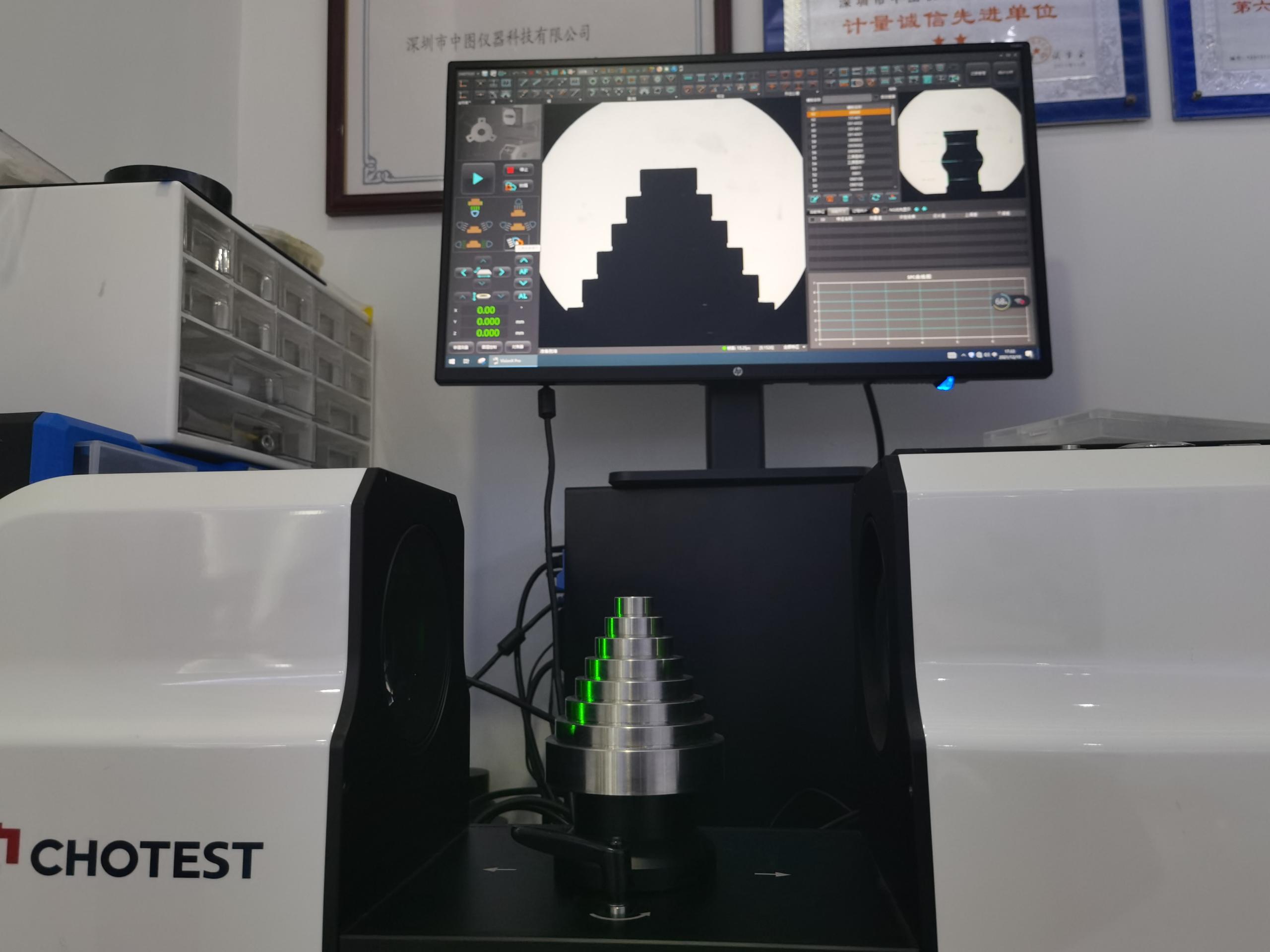
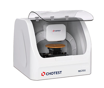
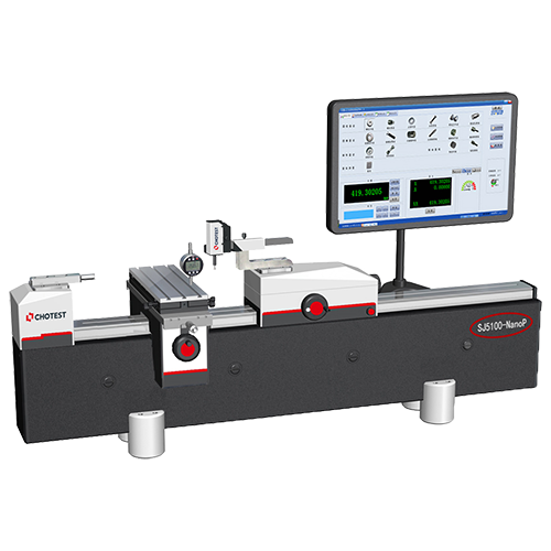
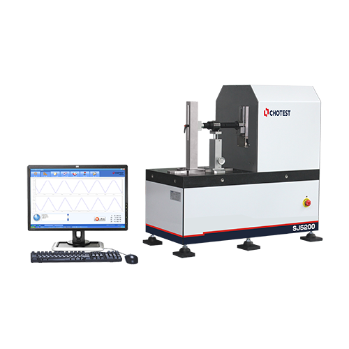
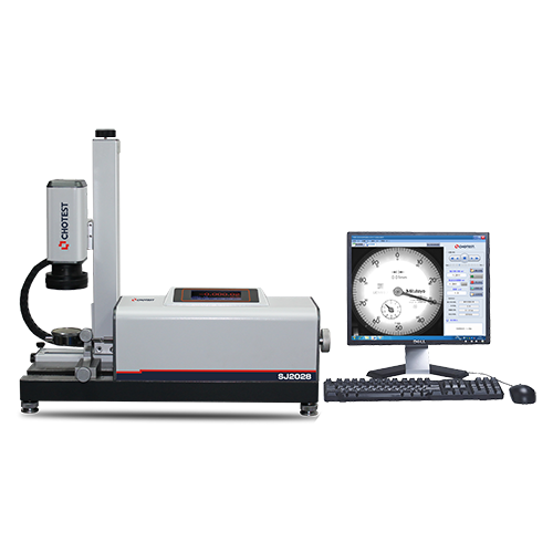
(Chotest Image measuring machine can measure shaft-like or cylindrical components – plastic or metal – for a variety of industries and applications.)
Optical 2D/2.5D systems are used in the automotive market to inspect turbochargers, engine valves, pistons, crank, drive and gear shafts. Both the aerospace and automotive sectors commonly use optical inspection for ball screws and shafts. Medical device manufacturers also use 2D/2.5D optical systems to inspect implants, bone screws and rotating instruments.
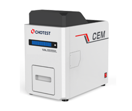
In the aforementioned example, our automotive manufacturer was using VX series loaded work cell designed and built to keep up with the 4,000 pieces per day. But, optical 2D/2.5D systems are equally at home performing audit inspections with manual operations being handled by a trained technician. When measuring cylindrical components, 2D/2.5D optical systems offer flexibility, speed and ease of use to be used in a variety of applications, whether a production environment or in a lab.