2021-11-30
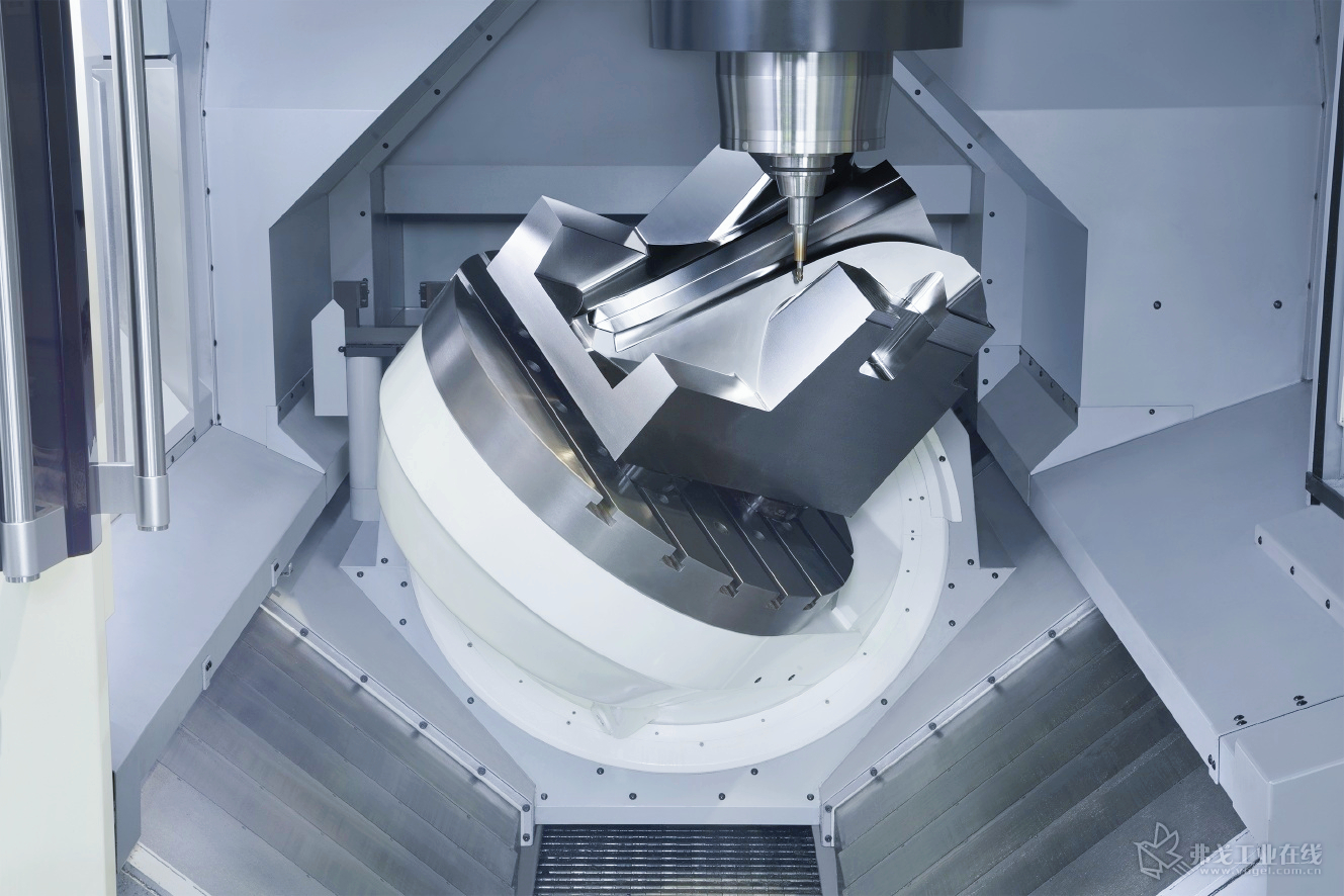
Traditionally, to calibrate the the rotary axis of a machine tool, we need to install an automatic precision turntable on its ratation center, to perform the calibration of the rotary axis. However, for the rotation center of the cradle-type five-axis machining center(C.O.R.), the situation is different.

It is restricted and has no connection parts, which leads to the need for more complicated brackets and collimation procedures to calibrate the axis,and this may increase the difficulty of calibrating the machine tool.
Today, we would show you how to measure the rotary axis accuracy with standard laser interferometer.
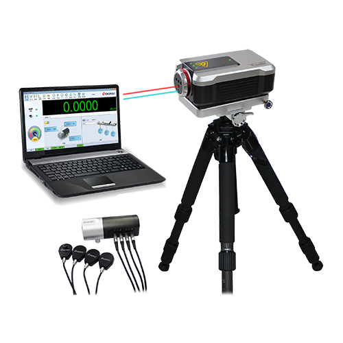
What you would need for the measurement,

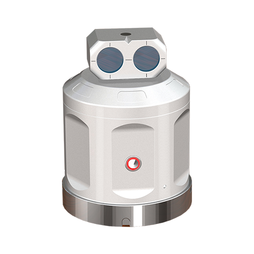
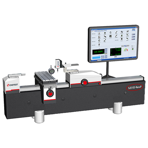
Install the WR50 Rotary Axis calibrator on the A-axis of the cradle-type five-axis machining center (it does not have to be installed in the rotation center) and perform the test. The eccentric axis measurement software will synchronize the movement of the linear axis and the rotation axis, and keep the laser continuously illuminated during the entire test. , Which can significantly simplify the installation hardware setting requirements.


Working Principle
The working principle of eccentric axis measurement is to use the synchronous movement of the linear axis and the rotary axis of the machine tool. As shown in the figure below, each rotary axis movement has a corresponding linear axis movement. It should be noted that even the same angular axis movement, the linear axis movement interval will be different. Please kindly ensure that the laser interferometer and the automatic precision turntable maintain alignment.

Matters need attention
Since one of the optical lens groups is fixed on the linear axis, the detected angle axis data will also include the linear axis error, such as the angle error shown below. For this reason, an additional, separate angle measurement should be performed simultaneously along the linear axis at the same stop position used during the initial synchronized movement. And then the two error files can be merged to eliminate the effect of linear axis angle errors, and then be true Shows the rotation accuracy of the rotary axis.

Chotest would always making efforts to find more efficient way of measuring. And hope to bring more benefits to our customers.
If you have any ideas of measuring, it's welcomed to share with us.